Previous lab. Return home. Next lab.
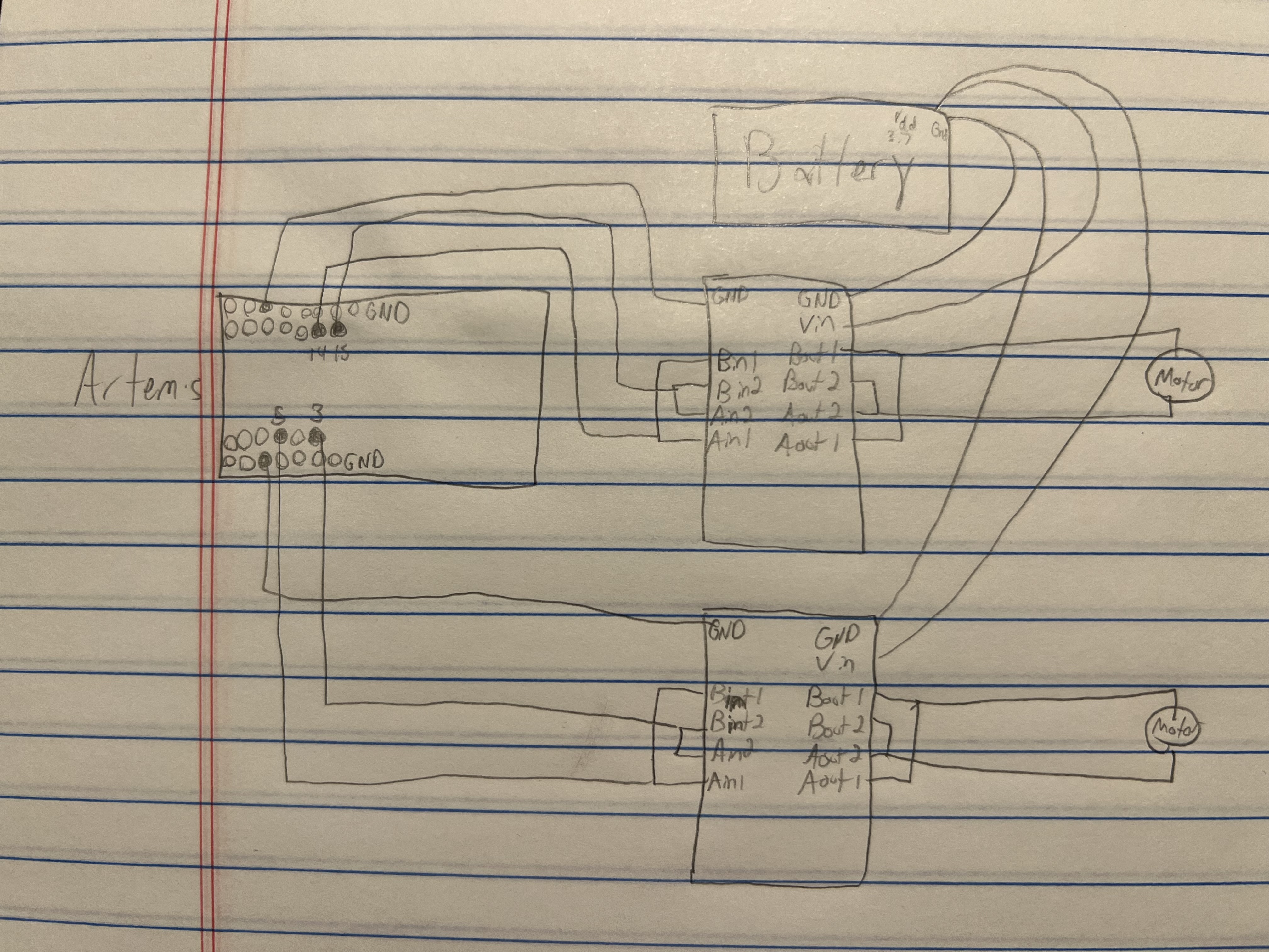
For the PWM, as of when I am writing this, I chose pins 2, 3, 14, and 15, as they are across from each other for the sake of symmetry. More importantly, though, they all have PWM capabilities. However, upon testing pin 2, it didn't seem to work, so I switched to pin 5. Below is a diagram showing this.
We power the Artemis and the motors/drivers with different batteries because the motors can draw a lot of current, especially when getting the motors started, turning the Artemis off and resetting program flow. With different batteries, this will be avoided.
In terms of choosing wiring, it was pretty hard to do this without much in the way of knowing what was inside the robot and what I might need to do. With this, I decided for many of my wires to just go with longer varieties, knowing that I can cut them later on. I used stranded wire to reduce wire breakages later on. A lot more decisions were made during the destruction and reconstruction of my robot, and those will be discussed later.
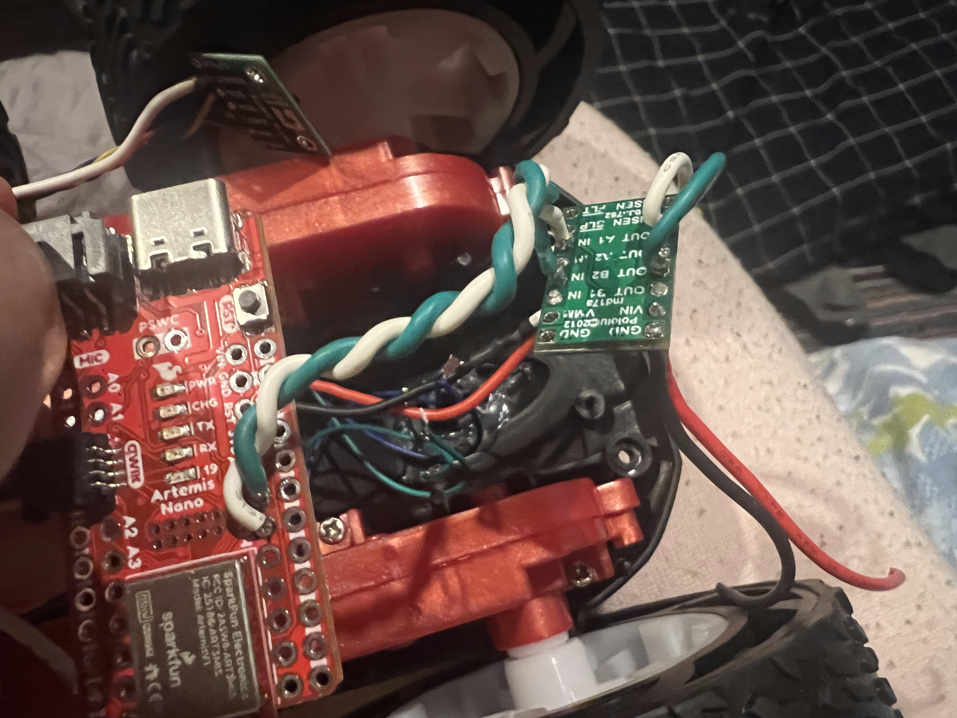
To connect the motor driver, input A1 was connected to input B1, input A2 was connected to input B2, and the same was done for outputs A1, B1, A2, and B2. I soldered the motor driver's pin input A1 and B2 to the Artemis's pin 14 and 15 respectively. In terms of these connections, I chose to use shorter wires because it seemed that the controllers and the Artemis won't be too far from each other in the final layout, though it was definitely hard to tell in that moment. I chose to twist the wires as much as I could within reason, as these are PWM signals, which vary rapidly, and could cause parasitic capacitance. Although I wonder if I twist too much, if it could somehow introduce inductance. So I didn't coil the twisted wires, I just twisted them. The power and ground were connected to the power supply (with a Voltage of 3.7 V, as that is what the batteries are. To drive with any other voltage wouldn't be accurate to the conditions they will ideally be under). Then the outputs were eventually connected to the motor. Much of this can be seen in the image below.
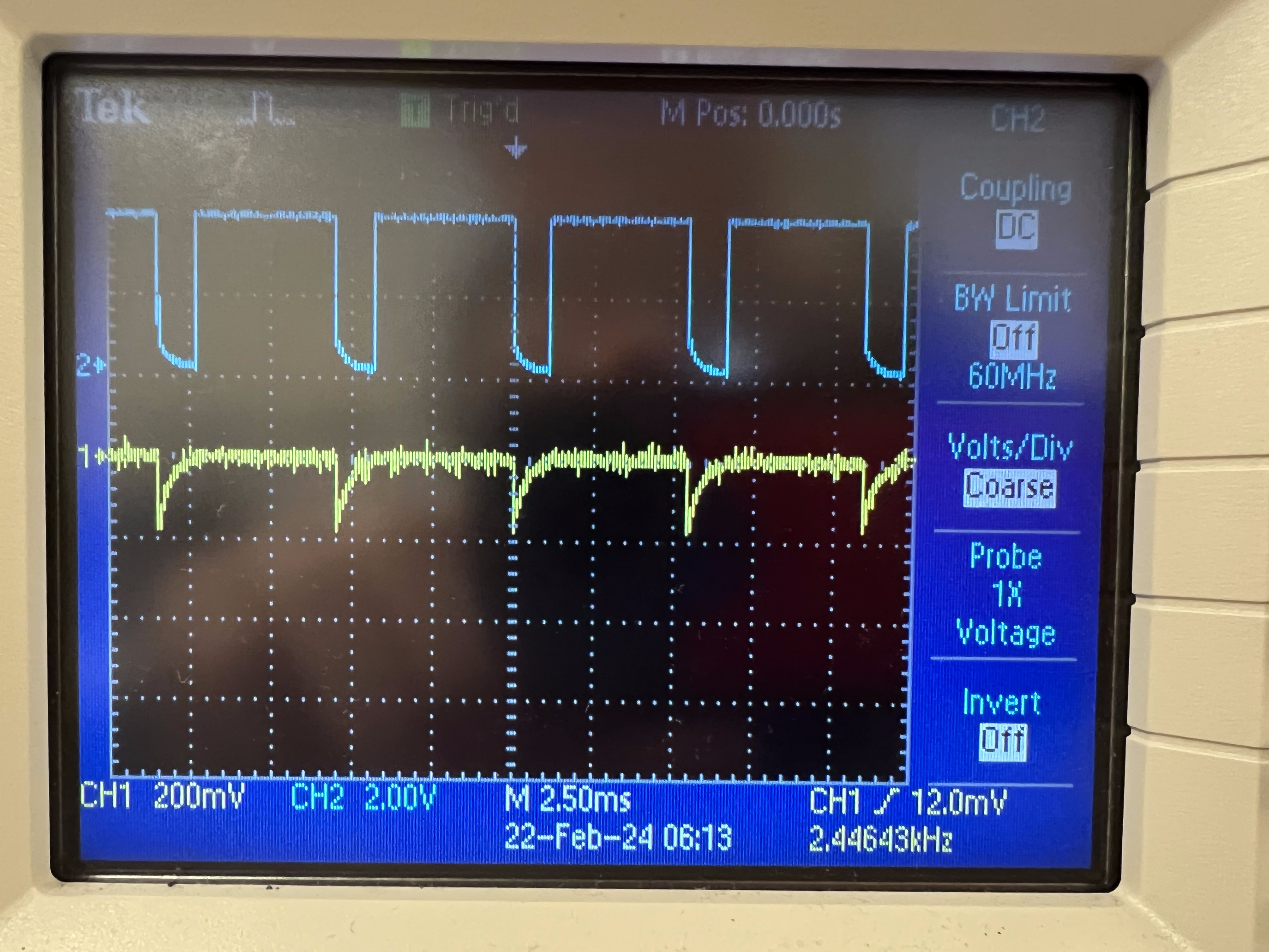
Then, the next step was to drive this with a PWM signal from the Artemis. While driving the motor driver, I connected the two outputs of the motor driver to the oscilloscope. The blue graph is the output I was driving from output 2 of the motor driver, and the yellow graph is the output I was not driving, connected to output 1 of the motor driver. This should be essentially 0 in function. These can be seen below. Motor driver ground, which is the power supply ground, was also connected to Artemis ground. This was driven at a PWM of 200, which can be seen in the width of the high parts of the duty cycle. This shows I am able to regulate the power on the motor driver output.
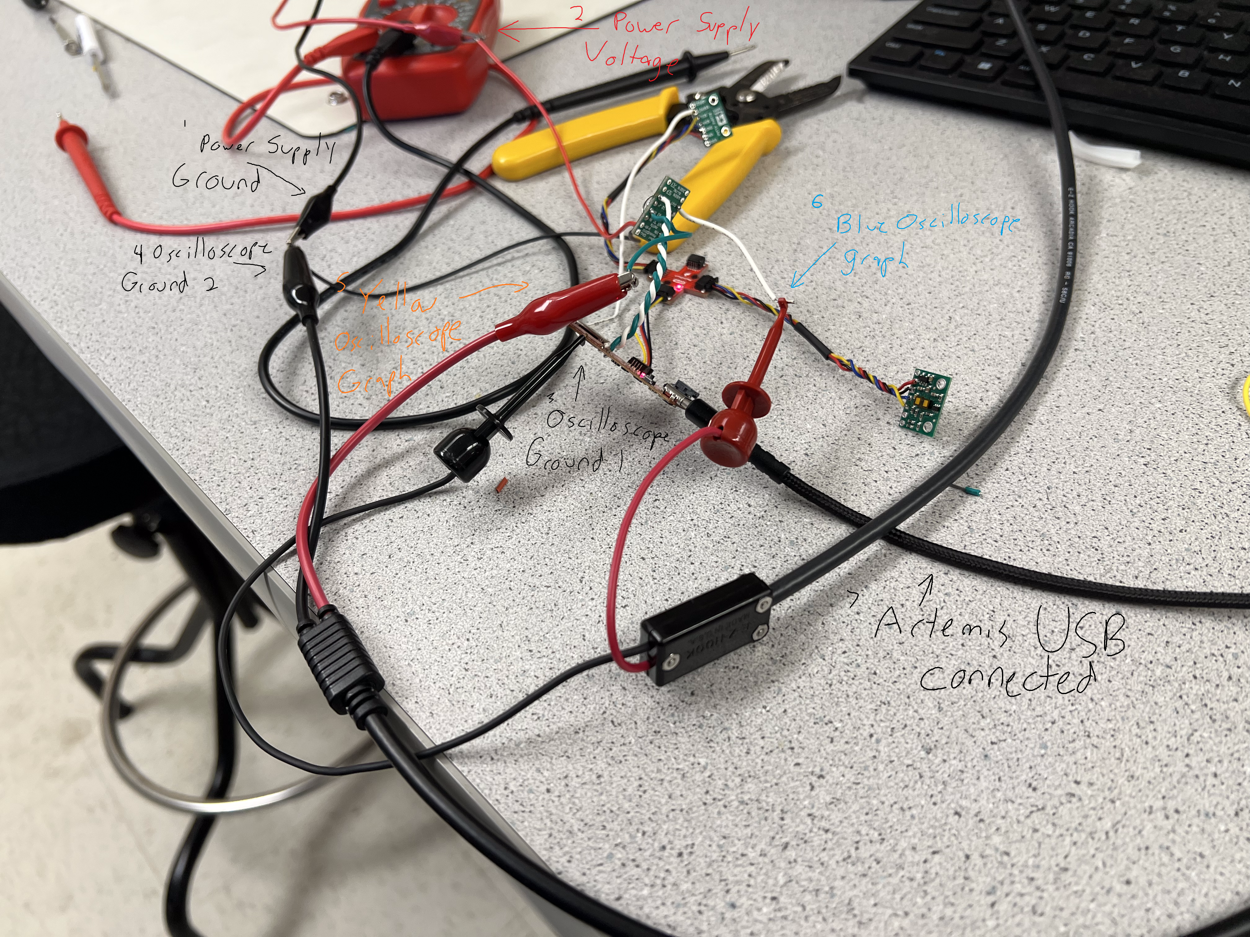
How I connected all of these up to the oscilloscope and power supply is shown in the images below. They aren't very clear, so I labeled how things are connected in the image. All the grounds (labeled 1, 3, 4 in the image) are connected. The oscilloscope grounds are internally connected, one of them (3) is connected to the Artemis, and the other one of them (4) is connected to the power supply ground (1). (1 and 4) are then connected to the motor driver ground pin. The power supply voltage (2) is connected to the motor driver's VIN pin. The aforementioned blue graph is driven by output 2 of the motor driver, and this can be seen connected to what is labeled (6) in the picture. The undriven output is 1 of the motor driver, and this is connected to the alligator clip labeled (5) in the picture. Lastly, I figured it would be helpful to indicate that the Artemis is powered via USB, as labeled (7).
The following is the single line of code I used to test the motor driver. The first value is the pin number 15 while the second is the PWM value, which was set to 200. This is just done in the setup() function, to allow the pin to constantly be driven indefinitely.
analogWrite( 15, 200 );
Below is a video of the first pair of wheels being driven by the Artemis while still connected to the power supply. As mentioned in the lab website, all grounds are connected to each other to form a universal ground. This will be so in the final wiring.
Below is the code snippet used to get that to work. It is the same analogWrite() line as before, still in the setup() function.
analogWrite( 15, 200 );
Below is a video showing that both pairs of wheels can be driven with just the battery and the Artemis. How exciting! They are all driven at a PWM of 200. Below is the code snippet, which is very similar to the previous ones.
analogWrite( 5, 25 );
analogWrite( 3, 0 );
analogWrite( 14, 0 );
analogWrite( 15, 25 );
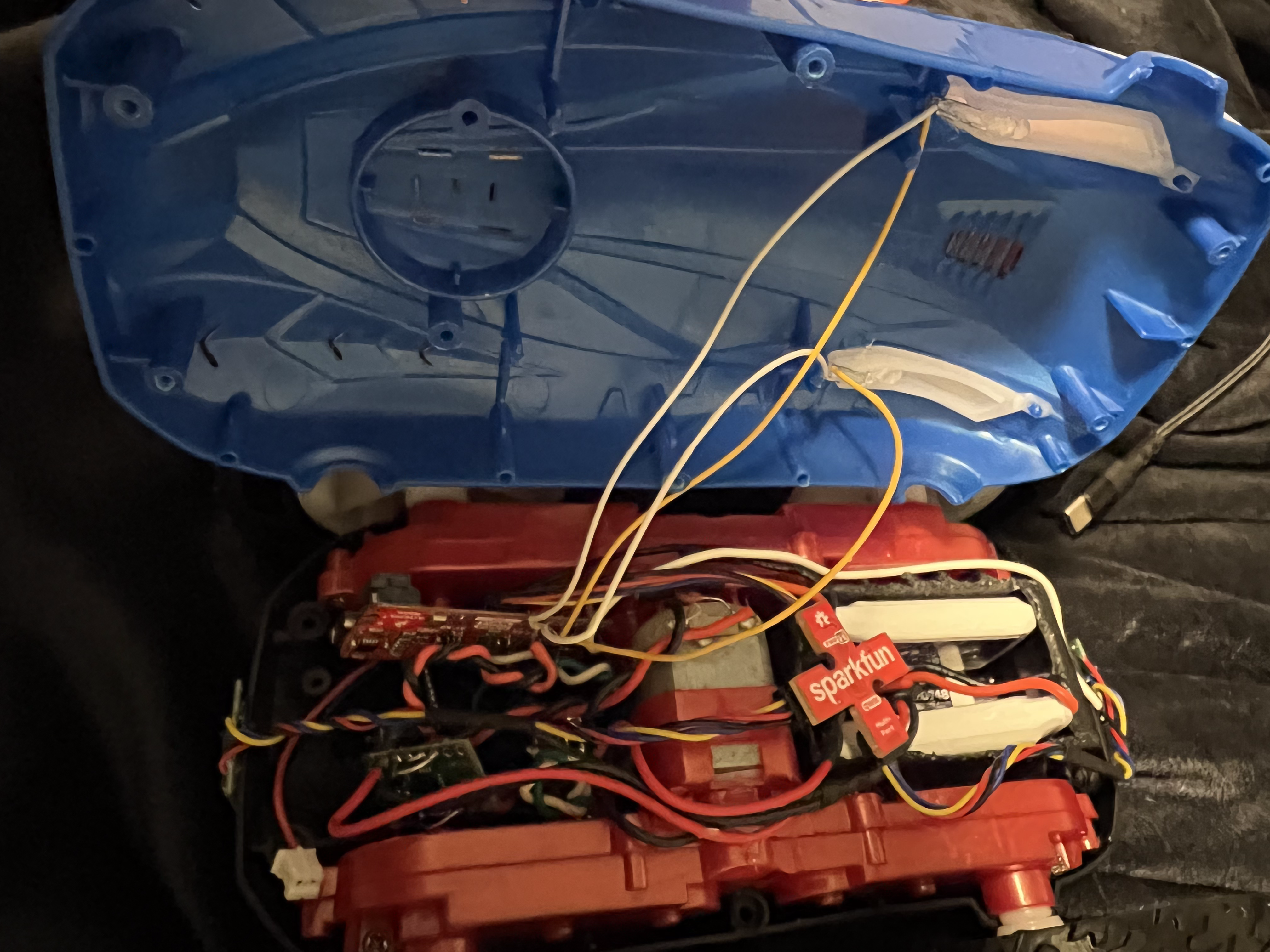
When it came to laying out the inside of the car, I was nearly completely lost beyond having a basic idea and basic thoughts of what might go where. And admittedly, I really wanted to be able to put the blue cover back on. I knew that would be a difficult task to add on top of that I wanted the distance sensors to be in the front and the back and the situation of not knowing what to do. With this, I ended up deciding to open up the robot and go from there.
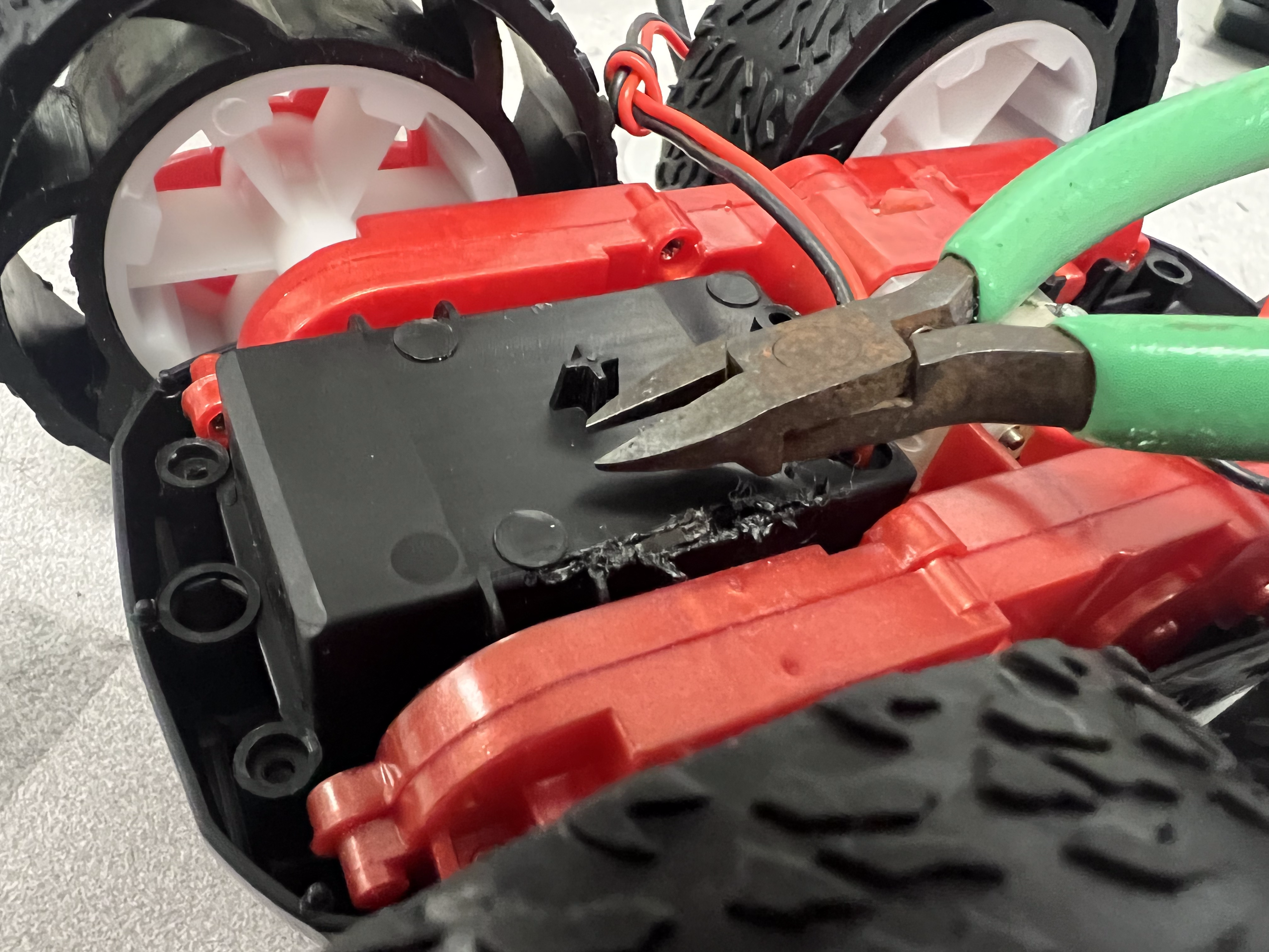
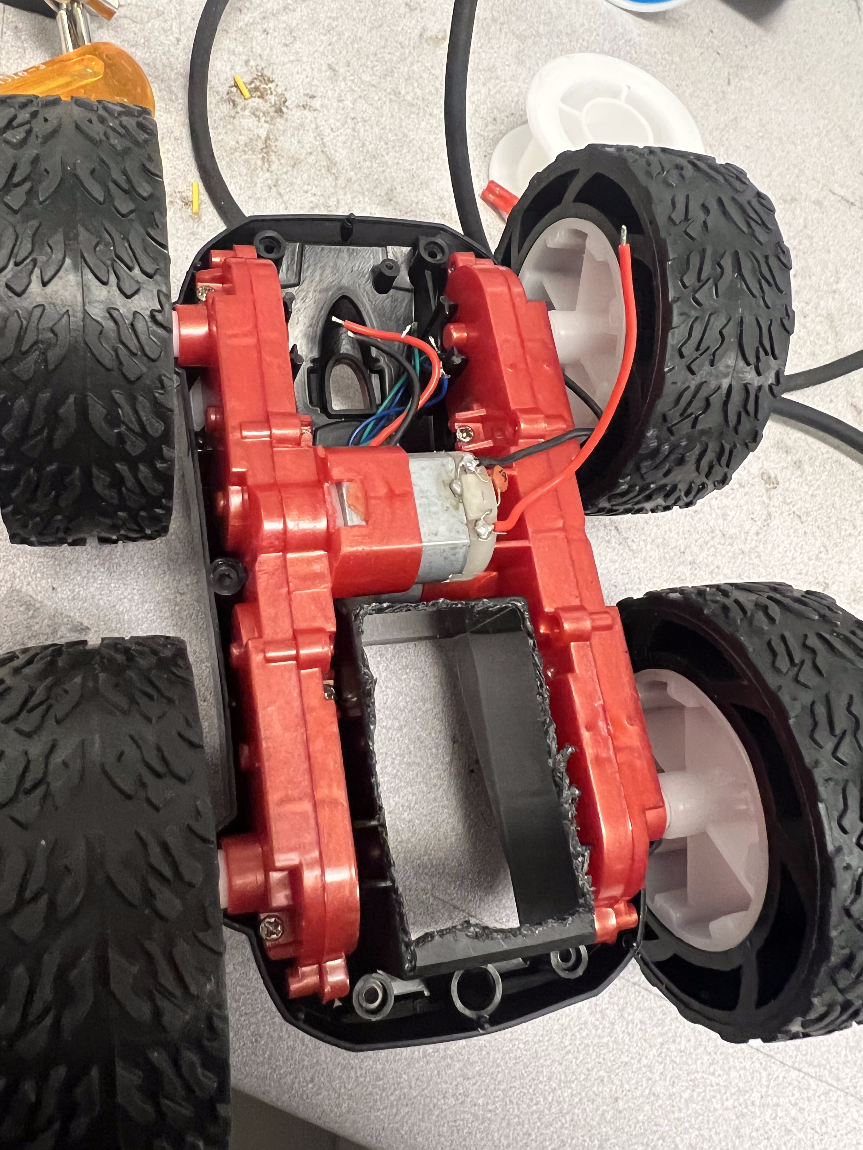
I kept looking at the battery compartment and wishing that it weren't there, as there would be so much room inside and it would make it so much easier to stick the blue cover back on. I eventually had the realization that I could possibly remove at least the bottom panel of the compartment. I wasn't sure how to do it. I eventually found the most effective way was to cut it all around with some cutting pliers. This was difficult but it certainly worked. This gained me another compartment with which to do things, though it did sacrifice a nice, flat surface which would have come in handy for the IMU. The result is shown below.
|
|
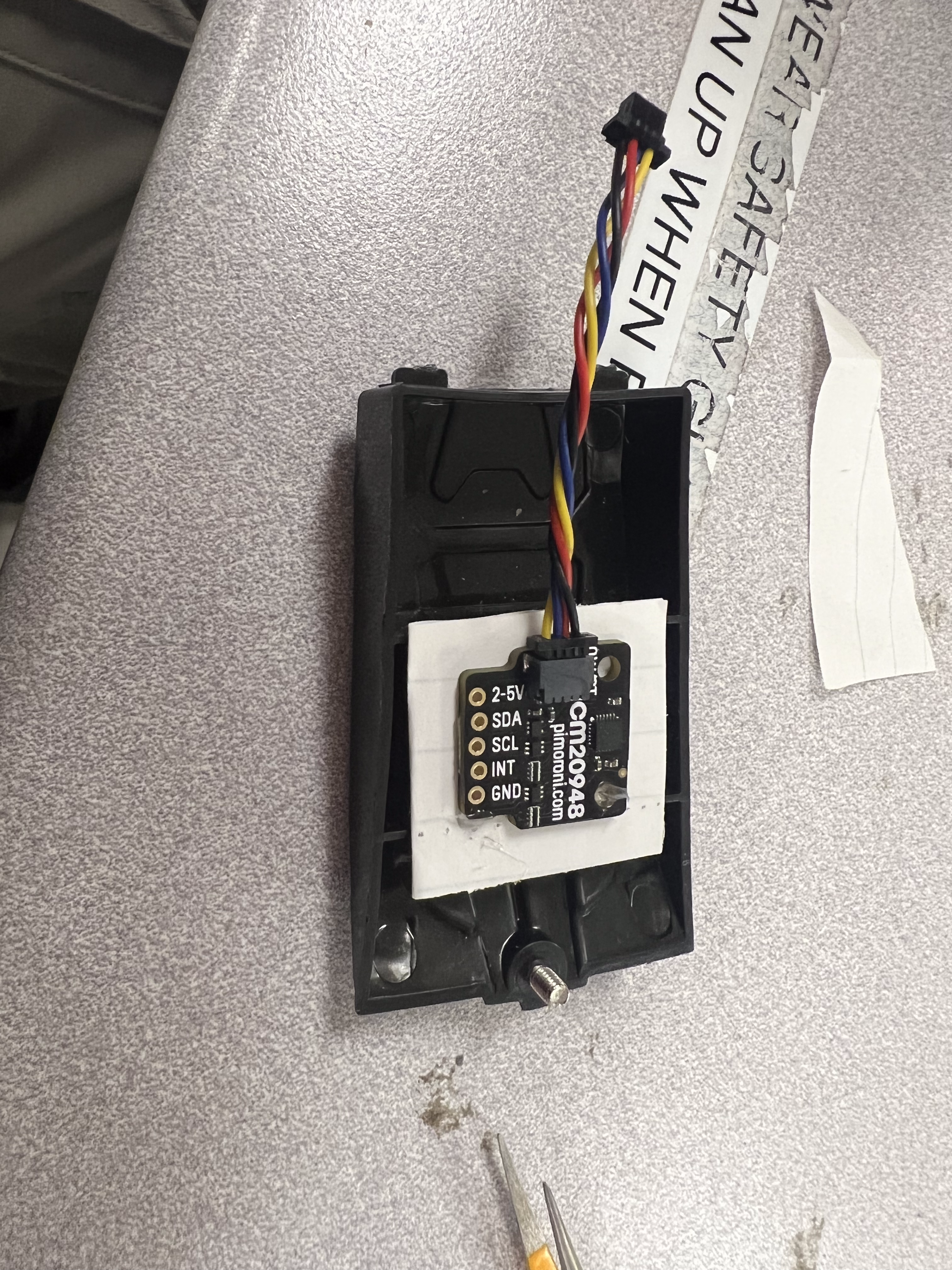
My solution to the flat surface problem was to create for myself another flat surface. To do this, I used the door of the battery compartment. It has horizontal barriers across it. These are just too far apart, though, to fit the IMU. I figured laying something across might be a good solution. However, something like paper would be too flimsy and probably wouldn't end up being as horizontal and solid as I wanted. To solve this, I took a piece of paper, folded it in half, put a blob of hot glue in between the halves, and pressed down, effectively forming a slab of hot glue, which was more firm than the paper, and large enough to lay across the plastic barriers and form a good surface for the IMU to lay upon.
The reason why I created my own flat surface was because the flat surfaces I had were all vertical, and when the IMU was vertical in previous labs, the other measurements were much less precise. When it was laying flat, however, within a reasonable range of motion, the measurements were fairly accurate. With this, I figured it would certainly be better to make for my robot a new horizontal flat surface, rather than settling for a vertical flat surface. Another consideration was to use the overhang I left in my cutting of the battery compartment (seen toward the bottom of the image above on the right) to act as a way to straighten it. But I wasn't fully settled on how I would be able to work with the batteries and any other components going in that compartment, so I just settled on this. It also would have likely been much less stable. I probably would have strongly considered it though, in hindsight.
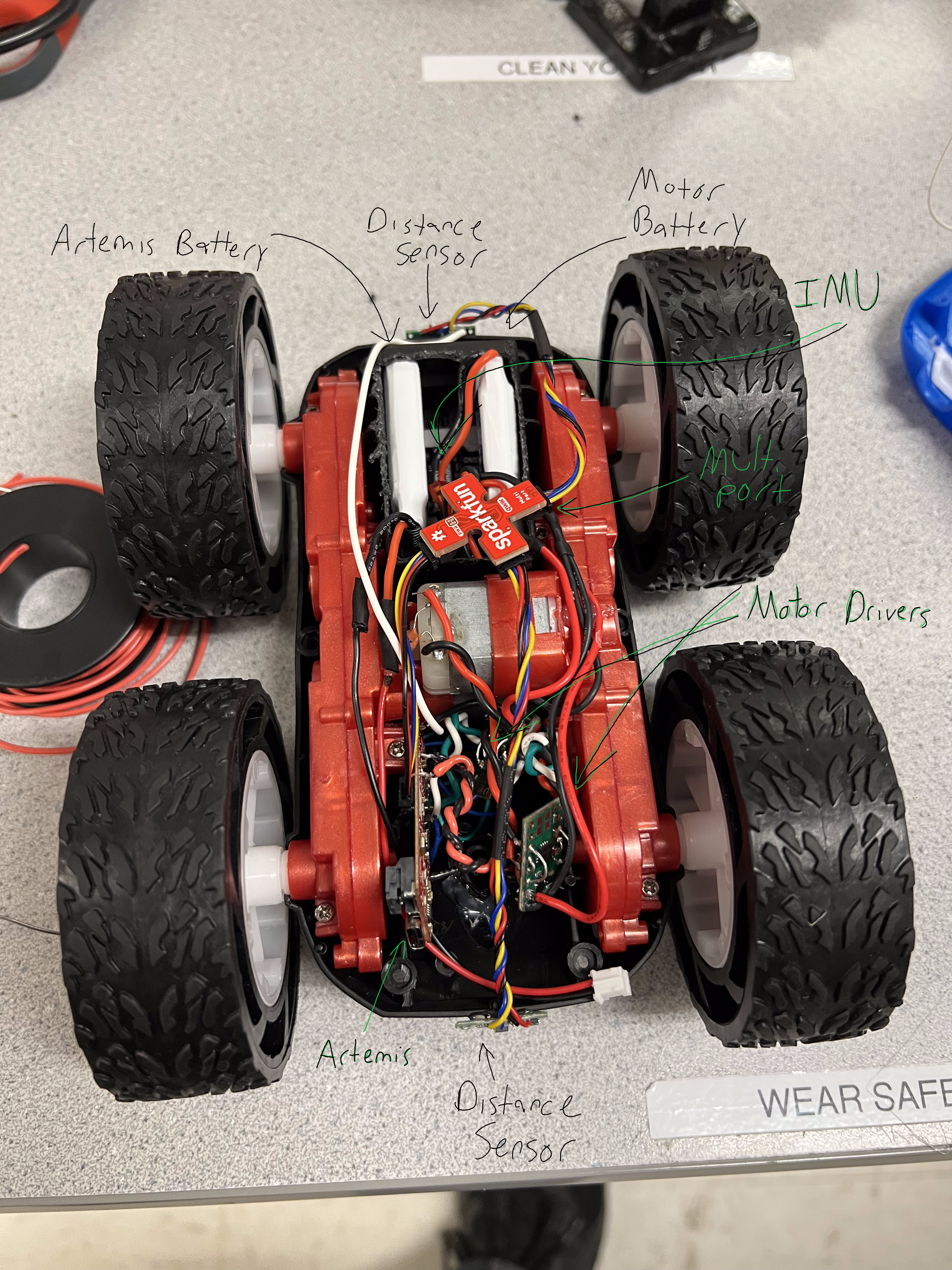
There was still another big problem, which was the stack of motors in the center of the insides of the car. This was mainly a problem in terms of the giant Qwiic multiport, which would not allow the top to close when it just sat there. The cables weren't long enough for it to sit in just one of the compartments I cut out for it, so I had to try to cleverly position it to allow it to just barely ride up on the motors, as seen in the image below. In a future lab, I hope to be able to extend the wires and allow the multiport to fit into the compartment.
Maybe it's a bit silly, but along with wanting the blue cover to fit back on, I really wanted the original LEDs to still light up. This was relatively simple, but it makes it a bit messier. For each set of the LEDs, it just took soldering the one of the pairs of wires to ground and the other pair to a pin on the Artemis. I did this for both the black bottom's pair of LEDs and the blue cover's pair of LEDs. It took a bit of effort to figure out which wire corresponded to ground and power, as I just soldered some of them without realizing it's a light emitting diode, meaning it mattered which was which. I had to do a little resoldering after that, but it definitely wasn't too bad. I now am able to control the LEDs as I wish.
// Set pin 4 and 11 as outputs, allowing us to activate them
pinMode( BLUE_LED, OUTPUT );
pinMode( BLACK_LED, OUTPUT );
Above and below are code snippits showing how I control the LEDs. These are both in the setup() function.
// Flash LED LED_FLASHES time(s)
for( int i = 0; i < LED_FLASHES; i++ ) {
// turn the LEDs on (HIGH is the voltage level)
digitalWrite( LED_BUILTIN, HIGH );
digitalWrite( BLUE_LED, HIGH );
digitalWrite( BLACK_LED, HIGH );
// wait for a time
delay( 200 );
// turn the LEDs off (LOW is the voltage level)
digitalWrite( LED_BUILTIN, LOW );
digitalWrite( BLUE_LED, LOW );
digitalWrite( BLACK_LED, LOW );
// wait for a time
delay( 200 );
}
|
Examining the video above, I can actually see that one of the two bottom LEDs do not go off, so that is something I will look into fixing in the future. But this is definitely a good proof of concept.
To better characterize the motors, it is important to know their lower limits. The right wheels' PWM seemed to be about 75. The left wheels' PWM seemed to be around 80. It was a bit finicky because it would sometimes go and get stuck for a second before building up the strength to continue a bit more. However, these values are just a springboard for what is to come. Using these values, in conjunction with the maximum 255 PWM value, I can create an adjusted value proportionally. We can map the real PWM values to going from 0 to 100, where 0 is off, and 100 is full power. This ends up looking like the following:
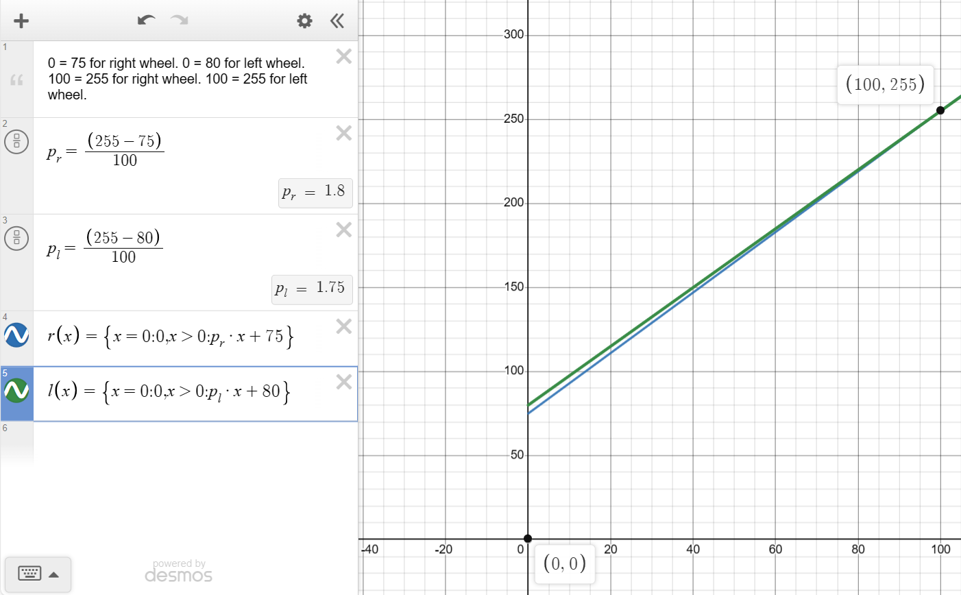
I ended up making it piecewise with a value of 0 mapping to 0, as I argue it is better to just turn off the motors when it is set to 0 instead of letting them struggle with a barely-not-enough PWM signal.
Starting with what I had derived earlier, I was able to incrementally work toward a mapping for the PWM values that functioned as I had hoped, meaning that they drove at approximately the same speed. I found the car kept veering to its left, meaning its right motors were sufficiently stronger than the left motors. I had adjusted the mapping originally to lower the slope by about 30%. This seemed to help. Then I lowered it by about 50% on top of the 30%. This didn't seem to make it much better. I then decreased it by 20% three times from the previous value. I realized that in decreasing the slope, there was diminishing returns. I brought the slope back to the 30% in combination with the 50%, as that was a realtively successful slope. It's likely then that what remained was a bad offset, so I brought it down by 10 PWM. This seemed to work a bit. I then brought it down to an offset of 62. This worked incredibly well, as shown in the video below.
The code I used to make this work is shown below. I used a Bluetooth command to set a timer and preset PWM signals based upon my found mappings. When the timer ran out, the wheels are turned off so as to prevent the robot from hurting itself.
case CHANGE_PWM_VALUE:
int int_c;
// Extract the next value from the command string as an integer
success = robot_cmd.get_next_value(int_c);
if (!success)
return;
temp_counter = int_c;
// Right wheels
// Forward driver
analogWrite( 5, right_pwm_map(5) );
// Reverse driver
analogWrite( 3, right_pwm_map(0) );
// Left wheels
// Forward driver
analogWrite( 15, left_pwm_map(5) );
// Reverse driver
analogWrite( 14, left_pwm_map(0) );
break;
It is incredibly poorly named as of now, because I started implementing a different command and just usurped the name for ease of implementation. All it does is, as previously mentioned, set the ascending timer and set the values for the PWM.
Being that the different pins might be able to write at different frequencies with the analogWrite() function, I thought it best to test them individually, driven at a PWM of 200. In doing so, I have found the following:
| Pin | Period (Milliseconds) | Frequency (Hertz) |
|---|---|---|
| 3 | 5.47 | 182.80 |
| 5 | 5.47 | 182.73 |
| 14 | 5.47 | 182.83 |
| 15 | 5.4 | 185.19 |
They all seem to have about a frequency of 183 Hz. I would argue that this is adequately fast for what we are trying to accomplish here, being that I was able to drive the car in a straight line doing so (and that we are instructed to use analogWrite in the first place).
In terms of potential benefits of manually driving a PWM signal to get faster speeds, it might lead to a smoother output. Though, for our purposes, this doesn't seem as though it would be much benefit.
In terms of the lowest PWM to maintain movement after breaking static friction, I got the value ... . I started at the PWM value to overcome static friction and decreased it until it stopped moving.
^^^ Unfortunately it got super late and I ended up calling it a night before getting to this point. Though, realistically, it would have been a value fairly lower than the value for overcoming static friction. Rafi had gotten 25 when he did the lab, and I likely would have gotten a similar figure.